This is part 3 of a 3 post series:
- Part 1: FrankenStatus Overview
- Part 2: Raspberry Pi config
So this part needs a massive disclaimer. 3 weeks in with learning how to work with an Arduino so it’s not going to look pretty. There are far more elegant approaches to the code I produced for this and with no previous experience with a soldering iron, well, let’s just say that I won’t be pursuing a career in precision soldering any time soon.
With that out of the way, let’s get going. I’ll first go through the wiring up of all the components, and then go through the code that makes it all happen.
This is the prototype that I build on a breadboard to make sure that it all worked:
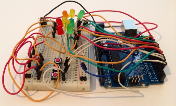
It’s actually pretty simple:
- 3 rows of 3 LED’s, each one individually addressable (on their own Arduino pin)
- 3 buttons
A potentially more helpful (but not necessarily correct) diagram of this is:
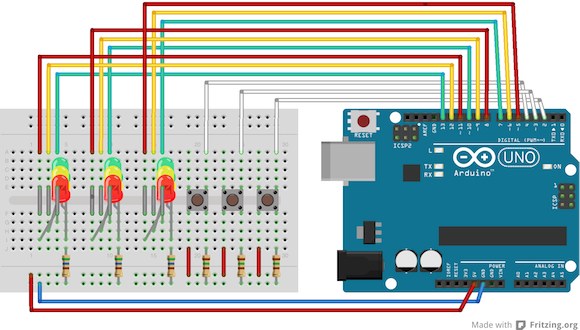
Two key differences between the diagram and the way that I actually wired it up:
- in both the prototype and in the final version, I connected the LED’s to one rail (on the breadboard) and grounded into one of the ground pins, and connected the buttons to another rail (on the breadboard) and grounded to a second ground pin on the Arduino. In the diagram I’m grounding all of the LED’s and buttons into the same rail and ground pin.
- The LED’s in the diagram may be the wrong way round. I have a fairly cavalier approach to how LED’s work – I plug them in and if they don’t come on, I switch them around the other way. I should probably try remember which pin takes current and which one is ground, but my method had served me fine so far. I did mention this wasn’t my day job, right?
So, all of the LED’s and buttons are grounded through the bottom rail, and the buttons get their current from the 5V pin, also connected via one of the bottom rails.
I’ve then bridged the bottom and top halves of the breadboard for each of the pins of the LED’s and then connected them to pins 13 down to 5 on the Arduino. The buttons are connected to pins 4, 3 and 2.
If, like me, you can’t solder, your final product might end up looking a bit like this:
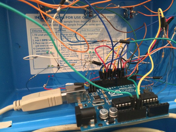
The mess along the top of the image are the underside of the switches, the mess running along the middle of the image are the pins of the LED’s sticking through from the top of the box. Remember how neat it looked when all closed up:
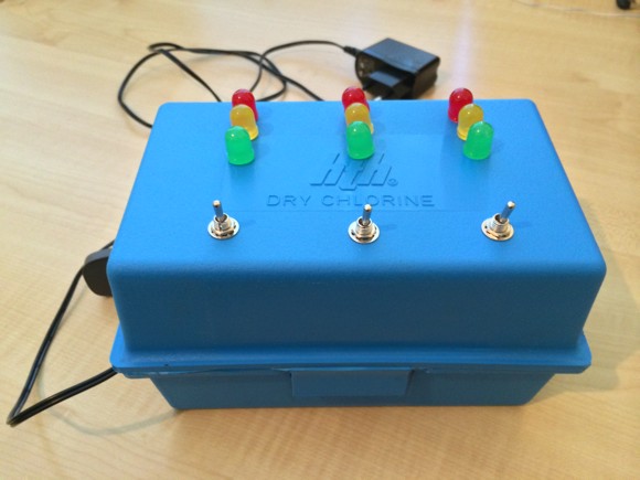
Lipstick on a pig.
If you’ve forgotten what the LED’s and switches do (or haven’t bothered reading the first of these posts), it’s probably best to get a refresher before diving into the code.
status_sketch.ino
String inputString = "";
boolean stringComplete = false;
int data[21];
These variables are used for the incoming data on the Serial port – the full string will be stored in inputString, the stringComplete variable is used to indicate that the full data string has arrived and the data array is used to store the individual elements in the string (once split).
int offTime = 200;
int eLED[] = {13, 12, 11};
int kLED[] = {10, 9, 8};
int hLED[] = {7, 6, 5};

int lowE = 13;
int medE = 12;
int higE = 11;

int lowK = 10;
int medK = 9;
int higK = 8;

int lowH = 7;
int medH = 6;
int higH = 5;

int butE = 4;
int butK = 3;
int butH = 2;

int butState = 0;
offTime is the amount of time that the LED’s are off for when flashing to indicate load. Remember when we retrieved and prepared the data to send to the Arduino, the LED’s flash at a speed to indicate number of people on the server. The time that the LED’s remain on is based on the value sent from the script, the amount of time that they are off is the value of this variable.
You can also see the beginnings of my refactoring here. Originally I had individual variables to store the pin numbers for the low, medium and high state LED’s for each server, but later decided to retain those in arrays.
The butState variable stores the number of the button (if any) currently on.
struct siteData {
  int idx;
  int cpu;
  int mcpu;
  int ram;
  int mram;
  int app;
  int ccu;
  double ela;
  int val;
};

siteData siteE;
siteData siteK;
siteData siteH;

double statusTime = 0;
int statusToggle = 0;
Because each site has a lot of data associated with it, I created a struct to store it all in. The idx variable contains the maximum value of all sent through for the current application. cpu and mcpu store average and max CPU values. ram and mcpu store average and max RAM values. app stores the AppDex value and ccu stores the current users on the site. The ela variable stores the time elapsed since the last time the LED was toggled between on/off and val stores the current on/off value for the LED’s for this site.
Because there are a lot of LED’s to switch on and off at different rates, I couldn’t use a delay in the main Arduino loop. So next time to toggle each of the LED’s is stored as time value in the future and each pass through the main loop just checks to see if we’ve reached that yet or not. This lets me flash the LED’s at arbitrary rates that are not related to one another.
We then get into the Arduino setup() function.
void setup()
{
  Serial.begin(9600);
  inputString.reserve(200);
  pinModes();
  defaultSites();
}
I’ve abstracted a lot of this away, so after connecting to the Serial port (to receive data from the Raspberry Pi) and reserving some RAM for the inputString, I call two functions: pinModes simply sets the modes for each of the pins on the Arduino and defaultSites populates the structs for each of the sites with default data.
On to the main() loop:
void loop()
{
  if (stringComplete) {
    setData();
  }
The first thing to do is check whether we have received a new string of data from the Raspberry Pi. If we have, call the setData() function.
Then, check if any of the buttons are on. If the are, store their value (number) in the butState variable:
  if (digitalRead(butE) == HIGH) {
    butState = 1;
  } else if (digitalRead(butK) == HIGH) {
    butState = 2;
  } else if (digitalRead(butH) == HIGH) {
    butState = 3;
  } else {
    butState = 0;
  }
We can then check to see if butState is set – if it is, then we know that we should show specific details to the site who’s button is being depressed:
  if (butState > 0) {
    siteData siteT;
    if (butState == 1) {
      siteT = siteE;
    } else if (butState == 2) {
      siteT = siteK;
    } else if (butState == 3) {
      siteT = siteH;
    }
Since a button has been pressed, copy the site data struct to a new site data struct that we will use for displaying on the LED’s. This is far more convenient that having a load of nested if statements later on. Looking back at the code I could probably have put this earlier up where we checked and set the buttonState variable. As I said, halfway through refactoring.
The first thing to do is check whether the current timestamp is greater than the timestamp we set as the future time to toggle the LED’s. If it has past, then set it to half a second in the future and toggle the value of statusToggle. Looking at the combination of bitwise operations again now, I’m wondering if something as simple as statusToggle = 1 – statusToggle would not have been a lot simpler.
We then check to see whether statusToggle is 0 or 1 – remember the button is pressed at this point, so we’re alternating between showing the maximum CPU/RAM and Appdex and showing the average CPU/RAM and Appdex. When statusToggle is 0, we show the average of CPU and RAM.
    if (millis() > statusTime) {
      statusTime = millis() + 500;
      statusToggle = (~(statusToggle&1))&(statusToggle|1);
    }
    if (statusToggle == 0) {
      if (siteT.cpu <=  20) {
        digitalWrite(lowE, HIGH);
        digitalWrite(medE, LOW);
        digitalWrite(higE, LOW);
        }
      else if (siteT.cpu > 20 && siteT.cpu <= 40) {
        digitalWrite(lowE, HIGH);
        digitalWrite(medE, HIGH);
        digitalWrite(higE, LOW);
      } else if (siteT.cpu > 40 && siteT.cpu <= 60) {
        digitalWrite(lowE, LOW);
        digitalWrite(medE, HIGH);
        digitalWrite(higE, LOW);
      } else if (siteT.cpu > 60 && siteT.cpu <= 80) {
        digitalWrite(lowE, LOW);
        digitalWrite(medE, HIGH);
        digitalWrite(higE, HIGH);
      } else if (siteT.cpu > 80) {
        digitalWrite(lowE, LOW);
        digitalWrite(medE, LOW);
        digitalWrite(higE, HIGH);
      }
I’m using the 3 LED’s to show 5 bands of the value, which is why sometimes there are two LED’s lit. After showing the CPU, show the RAM:
    // Show statu of RAM
      if (siteT.ram <=  20) {
        digitalWrite(lowK, HIGH);
        digitalWrite(medK, LOW);
        digitalWrite(higK, LOW);
      } else if (siteT.ram > 20 && siteT.ram <= 40) {
        digitalWrite(lowK, HIGH);
        digitalWrite(medK, HIGH);
        digitalWrite(higK, LOW);
      } else if (siteT.ram > 40 && siteT.ram <= 60) {
        digitalWrite(lowK, LOW);
        digitalWrite(medK, HIGH);
        digitalWrite(higK, LOW);
      } else if (siteT.ram > 60 && siteT.ram <= 80) {
        digitalWrite(lowK, LOW);
        digitalWrite(medK, HIGH);
        digitalWrite(higK, HIGH);
      } else if (siteT.ram > 80) {
        digitalWrite(lowK, LOW);
        digitalWrite(medK, LOW);
        digitalWrite(higK, HIGH);
      }
This part of the code executes is statusToggle is set to 1. When the button is pressed we’ll alternate statusToggle every 500 milliseconds. Here we show the maximum CPU and maximum RAM:
    } else {
      if (siteT.mcpu <=  20) {
        digitalWrite(lowE, HIGH);
        digitalWrite(medE, LOW);
        digitalWrite(higE, LOW);
      } else if (siteT.mcpu > 20 && siteT.mcpu <= 40) {
        digitalWrite(lowE, HIGH);
        digitalWrite(medE, HIGH);
        digitalWrite(higE, LOW);
      } else if (siteT.mcpu > 40 && siteT.mcpu <= 60) {
        digitalWrite(lowE, LOW);
        digitalWrite(medE, HIGH);
        digitalWrite(higE, LOW);
      } else if (siteT.mcpu > 60 && siteT.mcpu <= 80) {
        digitalWrite(lowE, LOW);
        digitalWrite(medE, HIGH);
        digitalWrite(higE, HIGH);
      } else if (siteT.mcpu > 80) {
        digitalWrite(lowE, LOW);
        digitalWrite(medE, LOW);
        digitalWrite(higE, HIGH);
      }

      if (siteT.mram <=  20) {
        digitalWrite(lowK, HIGH);
        digitalWrite(medK, LOW);
        digitalWrite(higK, LOW);
      } else if (siteT.mram > 20 && siteT.mram <= 40) {
        digitalWrite(lowK, HIGH);
        digitalWrite(medK, HIGH);
        digitalWrite(higK, LOW);
      } else if (siteT.mram > 40 && siteT.mram <= 60) {
        digitalWrite(lowK, LOW);
        digitalWrite(medK, HIGH);
        digitalWrite(higK, LOW);
      } else if (siteT.mram > 60 && siteT.mram <= 80) {
        digitalWrite(lowK, LOW);
        digitalWrite(medK, HIGH);
        digitalWrite(higK, HIGH);
      } else if (siteT.mram > 80) {
        digitalWrite(lowK, LOW);
        digitalWrite(medK, LOW);
        digitalWrite(higK, HIGH);
      }
    }
Irrespective of the toggle status, we always show AppDex on the third set of LED’s when the button is pressed:
    // Show status of Appdex
      if (siteT.app <=  20) {
        digitalWrite(lowH, HIGH);
        digitalWrite(medH, LOW);
        digitalWrite(higH, LOW);
      } else if (siteT.app > 20 && siteT.app <= 40) {
        digitalWrite(lowH, HIGH);
        digitalWrite(medH, HIGH);
        digitalWrite(higH, LOW);
      } else if (siteT.app > 40 && siteT.app <= 60) {
        digitalWrite(lowH, LOW);
        digitalWrite(medH, HIGH);
        digitalWrite(higH, LOW);
      } else if (siteT.app > 60 && siteT.app <= 80) {
        digitalWrite(lowH, LOW);
        digitalWrite(medH, HIGH);
        digitalWrite(higH, HIGH);
      } else if (siteT.app > 80) {
        digitalWrite(lowH, LOW);
        digitalWrite(medH, LOW);
        digitalWrite(higH, HIGH);
      }
When the button is not clicked, we show the maximum value out of all values for the three sites respectively. We’ll also use the millis() function, but instead of adding a standard 500 milliseconds when we were alternating between max and average, here we’ll use the value sent through based on the number of active users on the site. This will give each set of LED’s a different flashing speed.
} else {
    double tnow = millis();
    if (siteE.idx & lt; = 20) {
      digitalWrite(lowE, siteE.val);
      digitalWrite(medE, LOW);
      digitalWrite(higE, LOW);
    } else if (siteE.idx & gt; 20 & amp; & siteE.idx & lt; = 40) {
      digitalWrite(lowE, siteE.val);
      digitalWrite(medE, siteE.val);
      digitalWrite(higE, LOW);
    } else if (siteE.idx & gt; 40 & amp; & siteE.idx & lt; = 60) {
      digitalWrite(lowE, LOW);
      digitalWrite(medE, siteE.val);
      digitalWrite(higE, LOW);
    } else if (siteE.idx & gt; 60 & amp; & siteE.idx & lt; = 80) {
      digitalWrite(lowE, LOW);
      digitalWrite(medE, siteE.val);
      digitalWrite(higE, siteE.val);
    } else if (siteE.idx & gt; 80) {
      digitalWrite(lowE, LOW);
      digitalWrite(medE, LOW);
      digitalWrite(higE, siteE.val);
    }
    if (siteK.idx & lt; = 20) {
      digitalWrite(lowK, siteK.val);
      digitalWrite(medK, LOW);
      digitalWrite(higK, LOW);
    } else if (siteK.idx & gt; 20 & amp; & siteK.idx & lt; = 40) {
      digitalWrite(lowK, siteK.val);
      digitalWrite(medK, siteK.val);
      digitalWrite(higK, LOW);
    } else if (siteK.idx & gt; 40 & amp; & siteK.idx & lt; = 60) {
      digitalWrite(lowK, LOW);
      digitalWrite(medK, siteK.val);
      digitalWrite(higK, LOW);
    } else if (siteK.idx & gt; 60 & amp; & siteK.idx & lt; = 80) {
      digitalWrite(lowK, LOW);
      digitalWrite(medK, siteK.val);
      digitalWrite(higK, siteK.val);
    } else if (siteK.idx & gt; 80) {
      digitalWrite(lowK, LOW);
      digitalWrite(medK, LOW);
      digitalWrite(higK, siteK.val);
    }
    if (siteH.idx & lt; = 20) {
      digitalWrite(lowH, siteH.val);
      digitalWrite(medH, LOW);
      digitalWrite(higH, LOW);
    } else if (siteH.idx & gt; 20 & amp; & siteH.idx & lt; = 40) {
      digitalWrite(lowH, siteH.val);
      digitalWrite(medH, siteH.val);
      digitalWrite(higH, LOW);
    } else if (siteH.idx & gt; 40 & amp; & siteH.idx & lt; = 60) {
      digitalWrite(lowH, LOW);
      digitalWrite(medH, siteH.val);
      digitalWrite(higH, LOW);
    } else if (siteH.idx & gt; 60 & amp; & siteH.idx & lt; = 80) {
      digitalWrite(lowH, LOW);
      digitalWrite(medH, siteH.val);
      digitalWrite(higH, siteH.val);
    } else if (siteH.idx & gt; 80) {
      digitalWrite(lowH, LOW);
      digitalWrite(medH, LOW);
      digitalWrite(higH, siteH.val);
    }
Once the correct LED’s are set for the three sites, check the timestamp and if it has passed, either add the offTime we set earlier, or, if the LED is turning on, use the value passed through for the concurrent users. We use the val property to store the current on/off status of the LED and the lea property to store the current timestamp. Again, going through this code in one chunk has given me the benefit of recognising that earlier I added the interval to the current timestamp and tested against that, but here I’m using the current time less the last time I toggled the value and testing that against the interval. When I refactor I will standardise with a single method for handling the intervals.
    if (siteE.val == 0) {
      if ((tnow - siteE.ela) > offTime) {
        siteE.val = (~(siteE.val&1))&(siteE.val|1);
        siteE.ela = tnow;
      }
    } else {
      if ((tnow - siteE.ela) > siteE.ccu) {
        siteE.val = (~(siteE.val&1))&(siteE.val|1);
        siteE.ela = tnow;
      }
    }
    if (siteK.val == 0) {
      if ((tnow - siteK.ela) > offTime) {
        siteK.val = (~(siteK.val&1))&(siteK.val|1);
        siteK.ela = tnow;
      }
    } else {
      if ((tnow - siteK.ela) > siteK.ccu) {
        siteK.val = (~(siteK.val&1))&(siteK.val|1);
        siteK.ela = tnow;
      }
    }
    if (siteH.val == 0) {
      if ((tnow - siteH.ela) > offTime) {
        siteH.val = (~(siteH.val&1))&(siteH.val|1);
        siteH.ela = tnow;
      }
    } else {
      if ((tnow - siteH.ela) > siteH.ccu) {
        siteH.val = (~(siteH.val&1))&(siteH.val|1);
        siteH.ela = tnow;
      }
    }
  }
}
That’s the loop done. Everything else from here on are helper functions. The first one is the one that is called when we have a complete data string. Basically it’s a comma delimited string, ending in a ; character. Each chunk is popped into an array that we use at the end of the function to populate the three site structures.
void setData() {

    int numArgs = 0;

    int beginIdx = 0;
    int idx = inputString.indexOf(",");

    String arg;
    char charBuffer[16];

    while (idx != -1)
    {
        arg = inputString.substring(beginIdx, idx);
        arg.toCharArray(charBuffer, 16);

        data[numArgs++] = atol(charBuffer);
        beginIdx = idx + 1;
        idx = inputString.indexOf(",", beginIdx);
    }
    arg = inputString.substring(beginIdx);
    arg.toCharArray(charBuffer, 16);
    data[numArgs++] = atol(charBuffer);

    siteE.idx = data[0];
    siteE.cpu = data[1];
    siteE.mcpu = data[2];
    siteE.ram = data[3];
    siteE.mram = data[4];
    siteE.app = data[5];
    siteE.ccu = data[6];
    siteE.ela = millis();

    siteK.idx = data[7];
    siteK.cpu = data[8];
    siteK.mcpu = data[9];
    siteK.ram = data[10];
    siteK.mram = data[11];
    siteK.app = data[12];
    siteK.ccu = data[13];
    siteK.ela = millis();

    siteH.idx = data[14];
    siteH.cpu = data[15];
    siteH.mcpu = data[16];
    siteH.ram = data[17];
    siteH.mram = data[18];
    siteH.app = data[19];
    siteH.ccu = data[20];
    siteH.ela = millis();

    inputString = "";
    stringComplete = false;

   statusTime = millis() + 500;

}
The pinModes function is just a way to get all of the initialisation stuff out of the main setup() function and keep it neater.
void pinModes() {

  for (int i = 0; i < 3; i++ ) {
    pinMode(eLED[i], OUTPUT);
  }
  for (int i = 0; i < 3; i++ ) {
    pinMode(kLED[i], OUTPUT);
  }
  for (int i = 0; i < 3; i++ ) {
    pinMode(hLED[i], OUTPUT);
  }

}
Because the networking scripts all begin delayed, this function just populates the site structure with some initial data while waiting for the first data string to arrive.
void defaultSites() {

  siteE.idx = 1;
  siteE.cpu = 20;
  siteE.mcpu = 20;
  siteE.ram = 20;
  siteE.mram = 20;
  siteE.app = 20;
  siteE.ccu = 1000;
  siteE.ela = millis();
  siteE.val = 1;

  siteK.idx = 1;
  siteK.cpu = 20;
  siteK.mcpu = 20;
  siteK.ram = 20;
  siteK.mram = 20;
  siteK.app = 20;
  siteK.ccu = 1000;
  siteK.ela = millis();
  siteK.val = 1;

  siteH.idx = 1;
  siteH.cpu = 20;
  siteH.mcpu = 20;
  siteH.ram = 20;
  siteH.mram = 20;
  siteH.app = 20;
  siteH.ccu = 1000;
  siteH.ela = millis();
  siteH.val = 1;

}
The serialEvent function is called each time the Arduino receives data on the serial port. The data comes in chunks (not the whole thing at once) so we look for the ; character to indicate that the data has completed.
void serialEvent() {
  while (Serial.available()) {
    char inChar = (char)Serial.read();
    if (inChar == ';') {
      stringComplete = true;
    } else {
      inputString += inChar;
    }
  }
}
And that’s it. Not the prettiest code in the world, but it works. I’m in the process of refactoring it, will post that once done.